- All
- Product Name
- Product Keyword
- Product Model
- Product Summary
- Product Description
- Multi Field Search
Views: 212 Author: Site Editor Publish Time: 2025-06-27 Origin: Site


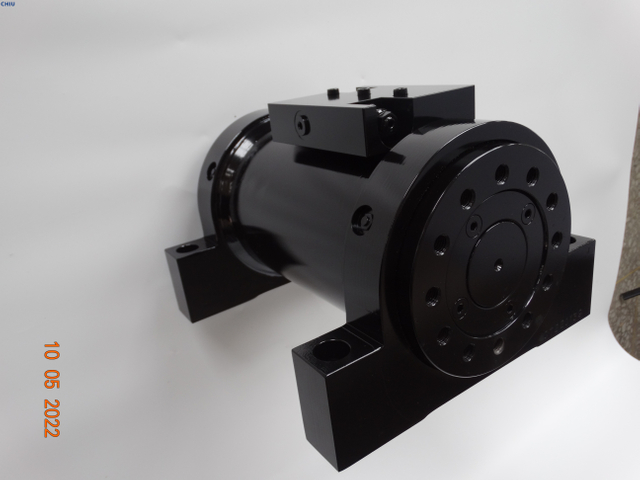
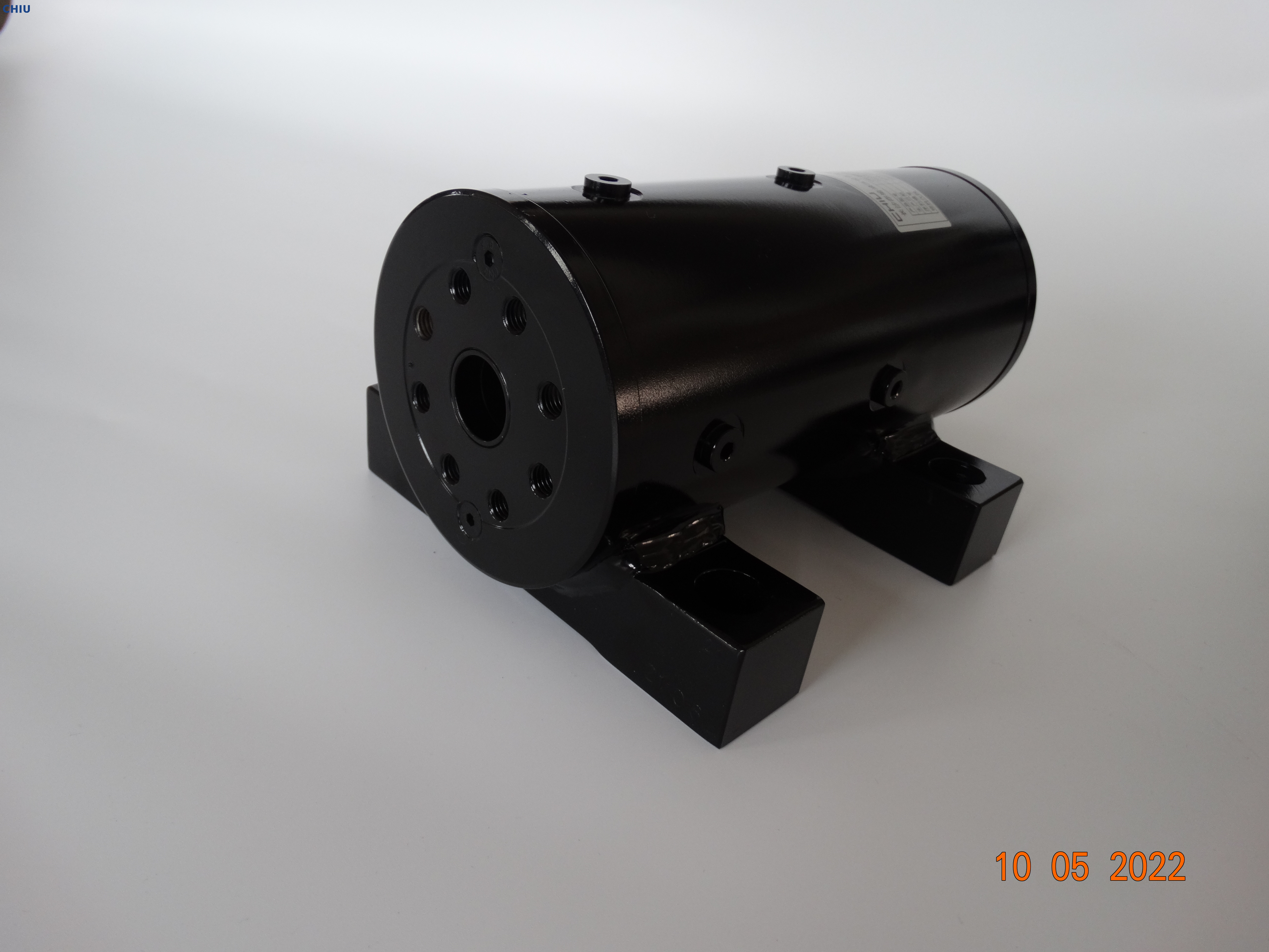
Hydraulic rotary actuators are critical components in countless industrial machines—from construction cranes and tunnel-boring machines to marine deck equipment and robotic welding cells. By converting pressurized hydraulic fluid into precise rotational motion, they deliver high torque in a compact package, enabling smooth, repeatable, and controllable turns even under heavy loads.
However, like any mechanical device, rotary actuators are subject to wear over time. Internal components—particularly pistons, vanes, and bearings—experience friction, erosion, and fatigue as they operate. Left unchecked, this wear degrades performance, reduces efficiency, and ultimately leads to unexpected downtime and costly repairs. In high-stakes industries such as offshore drilling, mining, and automated manufacturing, actuator failure can halt production, compromise safety, and incur significant financial losses.
A typical hydraulic rotary actuator consists of several key parts that interact under high pressure and speed. The three most wear-prone components are:
Pistons (or vanes in vane-type actuators)
Cylinder bores (or actuator body surfaces)
Bearings and bushings
Each of these plays a distinct role in converting fluid power into rotary motion, but each also experiences unique stressors that contribute to wear:
Pistons/Vanes slide or pivot against the bore surface, transmitting force from pressurized fluid.
Cylinder bores house the pistons/vanes and guide their movement; surface integrity is essential for tight sealing.
Bearings and bushings support rotating shafts and need consistent lubrication to reduce friction.
Wear in any of these areas can lead to loss of sealing efficiency, reduced torque output, increased backlash, and ultimately leakage or actuator seizure. Let’s examine each component in detail.
There are two common styles of hydraulic rotary actuators:
Piston (or axial piston) actuators, where multiple pistons arranged around the rotor convert fluid pressure into rotational force.
Vane actuators, in which a set of vanes mounted to the rotor slide within slots against the housing’s internal surface.
In both designs, the mating surfaces between piston/vane and bore must maintain a precise seal to prevent internal fluid bypass. High pressure—often 200–350 bar—presses these surfaces together with force, enabling high torque density. But that same pressure, combined with motion, leads to wear.
Abrasive Wear
Cause: Solid particles (dirt, metal shavings) in the hydraulic fluid become trapped between sliding surfaces.
Effect: Particles gouge the piston or vane surfaces and the bore wall, creating rough patches that accelerate further wear and degrade sealing.
Adhesive Wear
Cause: Metal-to-metal contact under high load can cause microscopic welding between piston/vane and bore, followed by tearing as they move.
Effect: Material transfers from one surface to another, leading to scoring and uneven wear patterns.
Erosive Wear
Cause: High-velocity fluid jets—particularly during rapid valve switching or cavitation—erode surfaces over time.
Effect: Pitting, thinning of vane edges, and eventual loss of cross-sectional strength.
Corrosive Wear
Cause: Contaminants or moisture in fluid reacting chemically with metals, especially in marine or outdoor environments.
Effect: Surface pitting, undermining sealing faces and promoting accelerated mechanical wear.
Increased internal leakage: Actuator rotates under load or drifts when holding position.
Reduced torque output: More fluid bypass means less effective pressure differential across the piston or vane.
Spongy or delayed response: Sloppy sealing allows fluid to compress, diminishing crisp motion.
Unusual noise or vibration: Scoring and loose tolerances create irregular motion or chatter.

The internal bore of the actuator housing provides the smooth, precisely machined surface against which pistons or vanes seal. Hardness, surface finish, and dimensional accuracy are critical.
Abrasive and Adhesive Wear: As with pistons, particles and micro-welds damage the bore.
Thermal Distortion: Heat buildup—especially in high-cycle applications—can cause bore ovality or taper, breaking the tight piston-to-bore fit.
Surface Fatigue: Repeated loading cycles can cause micro-cracks that propagate, leading to spalling or flaking of the bore lining.
Leak paths: Even small scratches compromise sealing, leading to fluid bypass.
Loss of concentricity: Pistons or vanes may tilt, causing binding or uneven wear elsewhere.
Increased friction: Rough surfaces raise drag, increasing power consumption and heat.
Bearings and bushings support the actuator shaft or rotor, absorbing radial and axial loads and maintaining alignment. Proper lubrication reduces friction and dissipates heat.
Hydrodynamic vs. Boundary Lubrication: Under light loads, a full fluid film separates surfaces (hydrodynamic), but heavy loads can lead to metal contact (boundary), accelerating wear.
Contamination: Abrasive particles in lubricant act like sandpaper.
Misalignment: Shaft deflection or housing distortion concentrates load on one side of the bearing.
Increased running clearance: Shaft play leads to backlash and position errors.
Overheating: Metal contact generates heat, further degrading lubricant.
Noise: Knocking or grinding sounds indicate metal-to-metal contact.
While each component experiences unique wear mechanisms, the underlying causes are often common:
Fluid Contamination
Inlet filters bypass or failure
Improper maintenance practices
Polluted reservoir environments
Inadequate Lubrication
Wrong fluid viscosity for operating temperature range
Degraded or oxidized fluid not replaced on schedule
Missing additive packages (e.g., anti-wear, anti-foam)
Overpressure and Shock Loads
Uncontrolled spikes during directional changes
Sudden load shifts (e.g., hitting a buried object)
Lack of pressure relief or surge dampers
Temperature Extremes
Overheating from continuous heavy cycling
Low-temperature viscosity increases friction at startup
Thermal cycling causing expansion/contraction fatigue
Poor Design or Manufacturing Defects
Surface finish not within specification
Improper material selection for application environment
Loose tolerances leading to misfits
To minimize internal component wear and maximize hydraulic rotary actuator reliability, follow these guidelines:
Install high-quality offline filters with 10–15 micron ratings to scrub fluid continuously.
Use pressure and return line filters rated to 3–5 microns in critical systems.
Maintain positive reservoir pressure to prevent air ingestion.
Implement oil sampling and particle counting: Regularly check ISO cleanliness codes and take corrective action if levels rise.
Choose hydraulic oil that meets OEM viscosity and additive recommendations for your temperature range.
Include anti-wear (AW) and corrosion-inhibitor additives to guard against metal-to-metal contact and moisture.
Adhere to scheduled oil changes: Replace fluids at intervals recommended by the actuator manufacturer or sooner if contamination is detected.
Monitor fluid condition: Track viscosity, acid number (TAN), and particulate load.
Install pressure relief valves set just above maximum operating pressure to protect vanes and pistons from spikes.
Use hydraulic accumulators or dampers to absorb sudden surges caused by fast directional changes.
Employ soft-start and soft-stop controls with proportional or servo valves to ramp pressures smoothly.
Incorporate heat exchangers or oil coolers on high-cycle or high-load systems.
Monitor operating temperatures with sensors and trigger alarms or automatic shutdown on over-temperature events.
Allow proper warm-up in cold climates: Use parallel heaters or bypass circuits to ensure fluid reaches optimal viscosity before full operation.
Specify appropriate materials: Hardened, nitrided, or coated surfaces on pistons, bores, and vanes resist wear better.
Tight machining tolerances and surface finishes (Ra ≤ 0.2 μm) ensure optimal sealing.
Ensure proper shaft alignment: Misalignment increases bearing loads. Use precision alignment tools at installation.
Avoid excessive side loads: Design linkages to transmit only intended torques, not bending moments.
Install vibration, pressure, and temperature sensors on actuators for continuous health monitoring.
Analyze trends: Abrupt changes in vibration or pressure consumption often precede wear-related failures.
Schedule minimally invasive inspections during planned downtime: Check clearances, seal condition, and fluid sample results.
Use data analytics and predictive algorithms to forecast component replacement timing, avoiding surprises.

A major tunneling contractor was experiencing actuation failures in their cutterhead steering units approximately every 500 operating hours—well below expected life. Failure analysis revealed severe vane and bore wear due to abrasive slurry ingress. By implementing the following measures, the contractor extended actuator life to over 1,500 hours:
Upgraded inlet and return filters to 3-micron ratings.
Switched to a hydraulic oil with specialized anti-wear and demulsifying additives.
Added a dedicated heat exchanger to maintain fluid temperature under 60 °C.
Installed an accumulator to dampen pressure spikes during rapid cutterhead reversals.
The result was a 70% reduction in downtime, significant cost savings on replacement parts, and improved tunneling progress rates.
Hydraulic rotary actuators deliver exceptional torque and precision in compact footprints, but their performance hinges on the integrity of internal pistons, vanes, bores, and bearings. By understanding the primary wear mechanisms—abrasion, adhesion, erosion, fatigue—and tackling root causes such as fluid contamination, inadequate lubrication, shock loads, and thermal extremes, operators can dramatically extend actuator service life.
Investing in robust filtration, proper fluid selection, pressure and temperature management, precision manufacturing, and proactive monitoring transforms actuators from consumable items into long-lasting, reliable assets. The rewards include reduced maintenance costs, minimized unplanned downtime, and greater confidence in mission-critical applications across construction, mining, offshore, and automation industries.
For specialized guidance on selecting, installing, and maintaining hydraulic rotary actuators tailored to your application, consider partnering with Changsha Chiyu Hydraulic Equipment Co., Ltd. Their engineering team offers comprehensive support—from initial specification through life-cycle maintenance—to help you achieve peak actuator performance and maximum return on investment.
Explore Chiyu’s product range and service programs at www.chiyu-hydraulics.com or contact their experts for a customized maintenance strategy.