
- All
- Product Name
- Product Keyword
- Product Model
- Product Summary
- Product Description
- Multi Field Search

Views: 0 Author: Site Editor Publish Time: 2026-05-22 Origin: Site


Engineering heavy-duty motion control presents a severe core challenge. You must achieve maximum torque output in strictly confined spaces. You also need to manage high multidirectional loads. Conventional linear cylinders demand excessive spatial footprints. They rely on bulky external pivot points and clevises. Traditional vane actuators face their own issues. They frequently fail under high-stress conditions due to chronic internal fluid leakage. The CY6 series rotary actuator emerges as a specialized solution. It operates reliably in severe operational environments where conventional mechanisms fail. This technical evaluation guide helps engineers and system integrators. You can use it to assess this advanced mechanism for upcoming machinery designs. We will explore its engineering fundamentals, strict performance benchmarks, and crucial real-world implementation realities.
Form Factor Efficiency: Utilizes a helical sliding spline mechanism to deliver up to 6700 Nm of drive torque without the bulky external linkages of linear cylinders.
Load Capacity: Engineered to handle massive radial and axial loads (up to 3900 KG simultaneously) directly on the shaft/flange.
Leakage Control: Outperforms traditional vane-style hydraulic rotary actuators with near-zero internal leakage, ensuring superior holding torque.
Integration Readiness: Built for the demanding realities of construction machinery, marine decks, and heavy automation, but requires careful thermal management due to inherent mechanical efficiency variables.
The minimalist engineering advantage of this unit lies in its internal structure. It relies on a single-moving-part mechanism known as a sliding helical gear. Fluid pressure acts directly on a specialized piston. This piston features highly machined helical splines. As the fluid pushes the piston linearly, the splines force the shaft to rotate. This direct conversion minimizes mechanical wear. It virtually eliminates zero-backlash issues over long-term use. You gain immediate, precise motion control without complex mechanical linkages.
When you compare it to linear cylinders, the spatial footprint reduction becomes obvious. A traditional cylinder requires extended rod clearance. It also needs external pivot points to convert linear push into arc motion. The helical actuator eliminates these requirements. It provides a compact, fully enclosed rotation point. This enclosed design lowers the risk of external contamination. It also prevents dirt or debris from causing mechanical binding on exposed rods.
Vane actuators have an industry-known vulnerability regarding internal bypass leakage. A vane sweeps across a cylindrical bore. Over time, high pressures push fluid past the vane seals. The CY6 solves this problem entirely. It uses a robust piston-and-seal architecture instead of a sweeping vane. This design achieves near-zero internal fluid bypass. It provides critical holding stability when you need to suspend massive loads in mid-air.
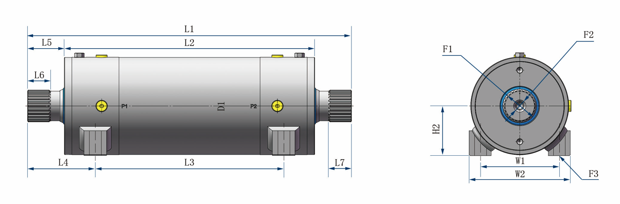
Engineers must match the operating envelope to system demands. The hydraulic rotary actuator provides an exceptional power density. We break down the torque and displacement metrics to clarify its capabilities. Drive torque ranges from 2,800 to 6,700 Nm at a standard operating pressure of 21 MPa. Holding torque represents its ability to lock a load in place. This capability scales up to a massive 14,300 Nm at 21 MPa. This metric proves essential for safety-critical load suspension.
Motion characteristics define how the unit physically interacts within a joint. Standard rotation angles span between 200° and 220°. Internal mechanical end-stops manage deceleration at the limits of this rotation. These heavy-duty stops prevent internal damage when the piston reaches the end of its stroke. They allow the unit to handle high-inertia deceleration safely.
Structural load limits elevate this unit beyond a simple motor. It features identical radial and axial bearing capacities. The robust internal bearings handle a maximum of 3900 KG simultaneously. This allows the actuator to serve directly as a primary structural hinge. You do not need secondary support brackets or external bearings.
Standardized interfaces ensure seamless integration into existing global hydraulic circuits. Output modes include sturdy flange options or splined shaft configurations. Engineers can match these interfaces to specific mounting needs. Standardized porting options include ISO, BSPP, and SAE threads. These global standards eliminate the need for complex custom pipe adapters.
Specification Parameter | Performance Benchmark | Engineering Implication |
|---|---|---|
Drive Torque (@ 21 MPa) | 2,800 - 6,700 Nm | Provides massive dynamic rotational force for heavy articulation. |
Holding Torque (@ 21 MPa) | Up to 14,300 Nm | Secures suspended loads with near-zero drift or internal bypass. |
Rotation Angle | 200° to 220° | Delivers ample sweep for tilt-rotators and boom articulation. |
Load Capacity (Radial & Axial) | Maximum 3900 KG | Functions as a direct structural hinge, eliminating external bearings. |
Construction machinery presents harsh, unforgiving environments. You face constant dirt ingress, violent shock loads, and erratic weather. The construction machinery actuator serves as the ideal joint for these applications. It excels in excavator tilt-rotators by providing high torque in a compact shell. Operators use it in rock drill feeds for reliable angular positioning. It handles heavy boom articulation smoothly. The fully enclosed design completely shields internal moving parts from abrasive dust and mud.
Mining and material handling industries rely on continuous uptime. Equipment failure halts production lines instantly. Engineers integrate these rotary units into critical chute controls to direct heavy ore. You will find them powering conveyor diverters in massive processing plants. Heavy-duty manipulators utilize their high holding torque to grab and suspend massive objects safely. The structural integrity of the CY6 withstands continuous, high-impact usage.
Marine and offshore environments introduce severe corrosion risks. Saltwater destroys unprotected steel components rapidly. You can adapt the heavy-duty rotary actuator for these harsh maritime applications. It works perfectly for deck cranes and heavy hatch covers. However, you must apply appropriate surface treatments. Heavy-duty epoxy or polyurethane coatings resist salt spray. For deep subsea operations, engineers must implement specific pressure compensation techniques. This ensures the internal seals survive extreme hydrostatic pressures.
Objective engineering requires a transparent look at system constraints. Mechanical efficiency variables represent a primary consideration. The helical conversion mechanism relies on sliding friction between spline teeth. Thermodynamic and mechanical efficiency typically ranges between 45% and 80%. This variance depends heavily on the external load, fluid viscosity, and operating speed. You must calculate system power requirements with these efficiency losses in mind.
Thermal management warnings are critical for successful integration. Frictional energy loss converts directly into heat. Continuous, high-frequency oscillation generates localized heat rapidly within the hydraulic fluid. You cannot ignore this thermal buildup. We strongly recommend establishing specific duty-cycle limits for rapid oscillation tasks. If you require continuous operation, you must integrate dedicated system coolers. Proper cooling prevents fluid degradation and protects internal seals from heat failure.
Filtration requirements dictate the long-term survival of the mechanism. Sliding splines and high-pressure seals demand pristine hydraulic fluid. You must adhere to strict fluid cleanliness standards. We recommend targeting ISO 4406 fluid cleanliness codes (e.g., 18/16/13 or better). Contaminated fluid acts like liquid sandpaper. It will cause premature wear of the helical splines. It will also degrade the high-pressure seals, ruining the zero-leakage advantage.
Shifting the procurement conversation toward precise engineering alignment ensures successful implementation. You must evaluate the component based on its mechanical suitability for your unique system. The enclosed, self-lubricating design reduces weekly maintenance labor requirements. Engineers need a reliable framework to evaluate the CY6 against project demands.
We provide a clear shortlisting logic to guide your decision framework. Follow these sequential steps to verify compatibility:
Calculate Required Torques: Accurately map your dynamic torque requirements against your static holding torque needs. Ensure your maximum load spikes do not exceed the 14,300 Nm holding limit at 21 MPa.
Determine Structural Load Requirements: Evaluate radial and axial forces at the joint. Determine if the 3900 KG capacity allows you to eliminate external support bearings. Removing redundant bearings simplifies your overall machine design.
Select the Appropriate Output Mode: Choose a Flange output for direct, rigid component mounting. Choose a Shaft output if your design relies on splined or keyed mechanical linkages.
Proactive maintenance extends the operational lifespan of high-pressure hydraulic components. A standardized leak troubleshooting SOP saves hours of diagnostic time. If you suspect piston or shaft seal failure, follow a strict diagnostic workflow. First, close the balance valves to isolate the actuator. Next, bleed any trapped air from the system. Rotate the mechanism to its hard limits and pressurize it to 21 MPa. Finally, monitor the return line for bypass flow. Any continuous flow indicates a compromised internal seal.
A preventative maintenance schedule keeps equipment running at peak performance. You must establish a baseline recommendation for field technicians. Implement visual seal inspections every week to catch external weeping early. Verify fastener torque settings monthly to ensure structural integrity under heavy vibration. Conduct fluid sampling intervals quarterly to verify ISO 4406 cleanliness targets remain intact.
Rebuild viability makes field repairs highly practical. When seals eventually wear out, you do not always need a factory refurbishment. Standardized seal kits are readily available. Field overhauls remain highly feasible for trained technicians. You can restore the actuator to its original zero-leakage specification without removing it entirely from the heavy machinery.
Maintenance Interval | Action Item | Target Metric / Observation |
|---|---|---|
Weekly | Visual Inspection | Check for external fluid weeping around shaft seals or flanges. |
Monthly | Fastener Verification | Ensure mounting bolts remain torqued to factory specifications. |
Quarterly | Fluid Sampling | Verify hydraulic fluid meets ISO 4406 cleanliness standards. |
Annually | Performance Diagnostic | Conduct a hard-limit bypass flow test at 21 MPa. |
The CY6 series rotary actuator is not a standard, generic component. It operates as a heavy-duty structural and driving element designed for maximum power density. It replaces bulky linear cylinders and leaky vane actuators by utilizing a sophisticated helical spline mechanism. It acts simultaneously as a structural hinge and a high-torque motor.
Successful implementation relies heavily on accurate engineering practices. You must conduct thorough load profiling to ensure structural limits are respected. Proper hydraulic thermal management remains essential to counteract mechanical efficiency variables. Maintaining strict fluid cleanliness guarantees a long operational lifespan.
Your next step requires verifying dimensional fit and torque curves. We recommend downloading the precise dimensional CAD models for your system layouts. Contact application engineering directly to verify custom torque-curve calculations. This ensures the actuator seamlessly matches your heavy machinery requirements.
A: Yes, but it depends on the output mode. Flange outputs require a specialized adapter plate to mount a standard rotary torque sensor. Direct-shaft outputs accept standard inline torque sensors using splined or keyed couplings. Always ensure the sensor can handle the massive holding torque limits to prevent sensor destruction during sudden load stops.
A: The rotation limit stems from the physical constraints of the internal piston stroke. In a helical sliding spline design, linear piston travel dictates rotational degrees. Extending the rotation to 360° would require an impractical, overly long actuator housing. Continuous 360° rotation requires gear-motor designs, not finite-stroke helical pistons.
A: No. It is strictly a high-pressure hydraulic rotary actuator. Operating it with compressed air will not yield the stated torque parameters. Furthermore, pneumatic operation presents severe safety and lubrication risks. The internal helical splines require the lubricity of hydraulic oil to prevent rapid mechanical destruction.
A: No homing calibration is required. It is a finite-rotation hydraulic device determined by hard internal mechanical stops. It inherently provides absolute position referencing without relying on electronic homing procedures. When the piston hits the end cap, the system definitively knows the actuator's physical location.


