- All
- Product Name
- Product Keyword
- Product Model
- Product Summary
- Product Description
- Multi Field Search

Views: 0 Author: Site Editor Publish Time: 2026-05-20 Origin: Site


Designing heavy-duty automation and lifting systems often forces a difficult compromise. Engineers must frequently balance output torque, physical footprint, and positional precision. Traditional mechanical linkages or linear cylinders consume vast amounts of space. They also introduce significant maintenance overhead over time.
When space remains limited but load demands stay high, conventional drives fail to deliver. Bulky external mechanisms increase system weight and create potential failure points in harsh industrial environments. Relying on outdated actuation methods compromises both machine reliability and overall design efficiency.
This article provides an evidence-based technical evaluation of the CY4 series rotary actuator. We detail operational limits, interface standards, and critical risk mitigation strategies. Buyers and systems engineers will discover actionable insights to finalize drive mechanisms for high-load, compact applications.
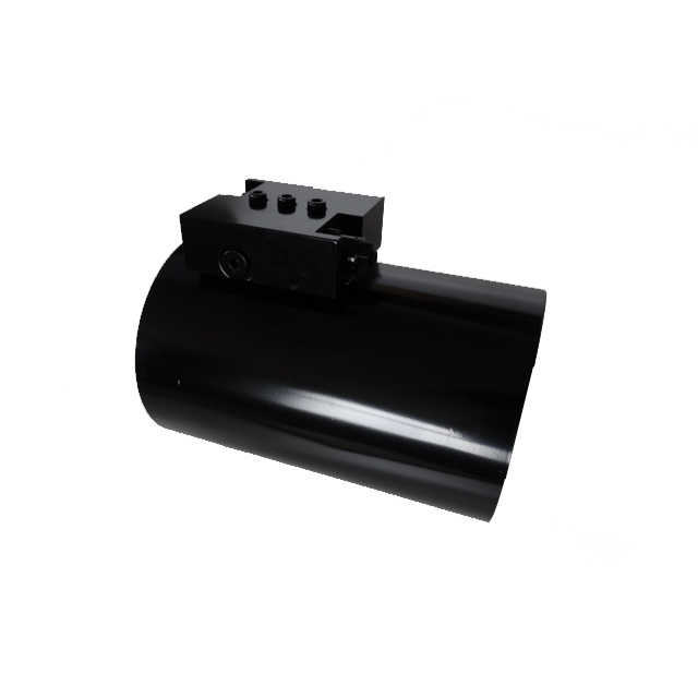
Form Factor vs. Output: The CY4 series utilizes sliding-spline (helical) technology to convert hydraulic pressure into high-torque rotation, eliminating the need for external linkages.
Standardized Integration: Features universally compliant portings (ISO-1179-1/BSPP and ISO-11926/SAE) and flexible mounting configurations (Foot, Flange, Saddle, Rail).
Precision and Reliability: Available in specific 180 degree actuator and 360 degree actuator models, engineered with quenched, hard-chrome plated rods to minimize internal leakage and resist radial/axial stress.
Implementation Reality: Typical torque conversion efficiency ranges between 45%–80%; reliable operation requires proper thermal management and balance valve integration.
Engineers specifying drive systems must understand the underlying physics of their chosen hardware. The CY4 relies on internal mechanics engineered for extreme force density. It abandons external levers entirely.
The core of this device relies on sliding-spline operation technology. You will often hear this referred to as a helical gear structure. Pressurized fluid enters the cylindrical housing. This fluid pushes a heavy-duty piston along a linear path. Instead of moving straight out like a standard rod, the piston engages internal helical splines. These splines force the piston to rotate as it travels linearly.
This combined motion translates direct fluid thrust into concentrated, high-strength shaft rotation. It achieves massive torque output internally. You do not need external moving parts, clevises, or pivot pins. The enclosed design inherently protects the drive mechanism from environmental debris.
Rotational limits define your application capabilities. You must match the actuator sweep to your mechanical constraints.
The 180 Degree Model: You evaluate the 180 degree actuator for spatial-restricted tasks. It excels at toggling, flipping materials, or opening heavy hatches where space prohibits full rotation.
The 360 Degree Model: You specify the 360 degree actuator for continuous articulation. It drives robotic joints, rotating platforms, and complex material handling arms requiring full circular reach.
Operational response matters deeply in precision automation. These devices exhibit highly sensitive starting conditions. They trigger reliable motion starting from fluid displacements as low as 20cc. This micro-displacement capability ensures smooth initiation without violent lurching.
System designers cannot look at torque as a single static number. You must break down the forces at play.
First, consider driving torque. We typically measure this at standard operating pressures, such as 21MPA. Driving torque represents the active rotational force available to move your payload. Next, evaluate holding torque. Holding torque resists back-driving when the system stops. It prevents heavy suspended loads from forcing the fluid backward through closed valves.
Finally, examine radial and axial load capacity. Suspended payloads hang off the shaft. This creates intense side-loading (radial) and push-pull forces (axial). The CY4 utilizes oversized internal bearings. These bearings withstand extreme directional stresses without permitting structural deformation or shaft deflection.
Upgrading a system requires justifying the technology shift. Engineers must compare sliding-spline designs against legacy pneumatic or hydraulic alternatives. The differences in volumetric efficiency and physical layout dictate system performance.
Traditional linear setups consume massive footprints. When you use a straight-push cylinder to create rotation, you must install clevises, mounting brackets, and complex lever arms. These extra linkages require clearance space. They also multiply potential points of mechanical failure.
The CY4 provides a self-contained rotary output. The conversion happens entirely inside the tube. This drastically reduces the physical footprint. You bolt the housing down, attach your payload to the shaft, and apply pressure. You eliminate external pinch points and simplify machine geometry.
Vane-style actuators offer an alternative rotary solution, but they carry inherent flaws under heavy loads.
Look at internal leakage benchmarks. Vane actuators rely on flat paddles sweeping against an internal cylinder wall. Over time, fluid slips past these vanes. We call this bypass leakage. It causes positional drift. The sliding-spline design approaches near-zero internal leakage. The piston seals tightly against the honed inner barrel, locking fluid in place and preventing load drift.
However, you must set realistic engineering expectations regarding torque conversion efficiency. Industry standards for helical actuators show efficiency sitting between 45% and 80%. Friction between the sliding splines and hydraulic fluid dynamics causes this loss. You must size your system pumps and relief valves to account for this variable baseline.
Actuator Type | Internal Leakage | Footprint | External Linkages Required? |
|---|---|---|---|
Helical Spline (CY4) | Near-Zero | Highly Compact | No |
Vane Style | High (Prone to drift) | Compact | No |
Linear Cylinder | Low | Large | Yes (Clevis, Lever) |
Procuring raw torque achieves nothing if you cannot connect the device to your hydraulic network. Successful deployment requires strict adherence to global interface standards.
Fluid power connections determine flow rates and peak pressures. Manufacturers standardize these ports to ensure global compatibility.
Housing Port Threads: The primary fluid entry points utilize ISO-1179-1 / BSPP thread standards. You typically see sizes ranging from 1/8 to 1/4 inch. This accommodates standard European and global hydraulic fittings.
Valve Port Standards: Auxiliary control interfaces align with ISO-11926 / SAE standards. These usually feature 7/16 inch threading, catering heavily to North American equipment integrations.
Attachment methods govern how effectively you transfer force to the chassis.
First, evaluate output modes. Shaft output features a keyed rod projecting from the housing. It suits direct couplings and gear interlocks. Flange output provides a flat, bolt-ready face. It works best when attaching heavy, rigid payloads directly to the rotation center.
Next, evaluate installation modes. You must select the right anchor type based on structural chassis constraints:
Foot Mount: Anchors the device firmly to a flat base plate.
Flange Mount: Secures the housing through a bulkhead or dividing wall.
Saddle Mount: Cradles the cylindrical body for high-vibration environments.
Rail Mount: Allows adjustable positioning along linear tracks prior to lockdown.
Rotary systems face violent kinetic forces during deceleration. Integrating specific valving protects the hardware.
You must integrate balance valves to stabilize the hydraulic rotary actuator. Negative loads occur when gravity pulls the payload faster than the pump pushes fluid. This causes cavitation inside the cylinder. A balance valve creates artificial back-pressure. It controls the descent, prevents runaway actuation, and locks the load securely when flow stops.
Heavy machinery breaks down when engineers ignore microscopic wear factors. You must proactively manage fluid boundaries, metallurgical stress, and heat accumulation.
Fluid slip ruins positional accuracy. We acknowledge three primary failure modes driving internal leakage. First, operators subject the system to severe pressure overloads. Second, poor internal polishing destroys seal integrity during assembly. Third, manufacturers install inferior seal kits.
We implement a strict CY4 mitigation strategy. We utilize premium US-standard seal kits formulated for high-friction durability. Furthermore, we apply precision CNC machining and ultrasonic cleaning processes. These manufacturing controls remove abrasive micro-particles and maintain incredibly tight internal tolerances.
Shock loads transmit immense shearing forces through the shaft. Weak metals snap under these conditions.
We establish a rigorous metallurgical baseline. The core components utilize 45# steel. We subject this steel to advanced Quenching and Tempering protocols. This thermal treatment balances optimal surface hardness with internal structural toughness, preventing brittle fractures.
Additionally, we apply hard chrome plating to the rods. Hard chrome achieves two critical goals. It significantly enhances seal friction compatibility, allowing fluid movement without tearing the polyurethane. It also massively increases wear resistance against external abrasives.
Friction generates heat. When sliding splines mesh under high loads, they transfer kinetic energy into the hydraulic fluid.
We issue a realistic warning regarding heat generation. High-frequency duty cycles rapidly elevate oil temperatures. Hot fluid loses viscosity. Thin oil leaks past seals more easily and provides less lubrication. For continuous-duty applications, engineers must specify dedicated fluid cooling loops. Keeping fluid temperatures within specified bounds guarantees consistent torque efficiency.
Specifying the wrong model leads to immediate mechanical failure or wasted system capability. You must match the actuator mathematically to the operational environment.
Designers scale their choices across a wide range of available configurations, specifically Models 2 through 27. You must calculate expected payload momentum.
This goes beyond simple weight. You must evaluate moment capacity. When you bolt a long arm to the shaft, the payload acts as a lever. It multiplies force against the internal bearings. We call these cantilever mounting forces. You must select a CY4 model where the rated moment capacity exceeds your peak dynamic cantilever load. Ignoring this calculation destroys internal splines rapidly.
Industrial machinery frequently operates outdoors or inside corrosive chemical plants. Cast aluminum or steel housings rust if left unprotected.
You must establish criteria for harsh environments. Specifying epoxy coatings or UV-resistant polyester powder coatings shields the external housing from oxidation and chemical degradation.
Furthermore, assess operating temperature bounds. Extreme cold alters fluid dynamics. You must require low-temperature greases on external seals. You also must specify specific hydraulic fluid viscosities. Thick, frozen oil causes cavitation and sluggish response times. Proper environmental mapping ensures year-round operational stability.
Engineering complex automation requires reliable, power-dense components. The CY4 series represents the optimal motion control actuator for heavy-duty, space-constrained environments. It delivers absolute load holding capabilities and exceptionally high torque without the spatial penalty of traditional linear cylinders.
System designers must transition from theoretical planning to actionable integration. We prompt engineers to download the full dimension diagrams and detailed datasheets. Consult directly with application engineering teams to verify exact torque requirements and confirm appropriate balance valve sizing prior to final procurement.
A: Internal leakage is primarily caused by pressure overloads exceeding the hardware rating, degradation of substandard seals, or internal scoring from fluid contamination. The CY4 combats these specific failures through rigorous hard-chrome plating processes, precision internal polishing, and the implementation of high-grade, US-standard seal kits.
A: Like most helical hydraulic designs, the torque conversion efficiency practically ranges from 45% to 80%. This accounts for internal sliding friction when converting hydraulic thrust into rotational torque. Engineers performing system sizing must mathematically account for this baseline loss.
A: While the physical mechanical hard-stop is permanently set at 180 degrees, you achieve intermediate angle control differently. Holding specific intermediate positions relies on external proportional valving and sensory feedback loops integrated directly into your broader motion control system network.
A: Yes, balance valves are highly recommended for safe operation. They precisely control the deceleration of heavy payloads, hold the actuator securely in position when fluid flow stops, and prevent dangerous hydraulic system run-away under overhauling or negative loads.


